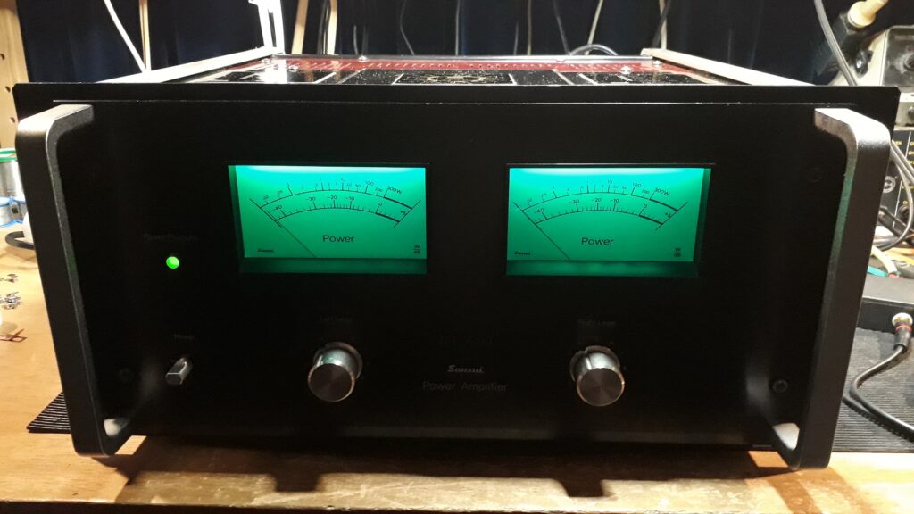
BA5000:
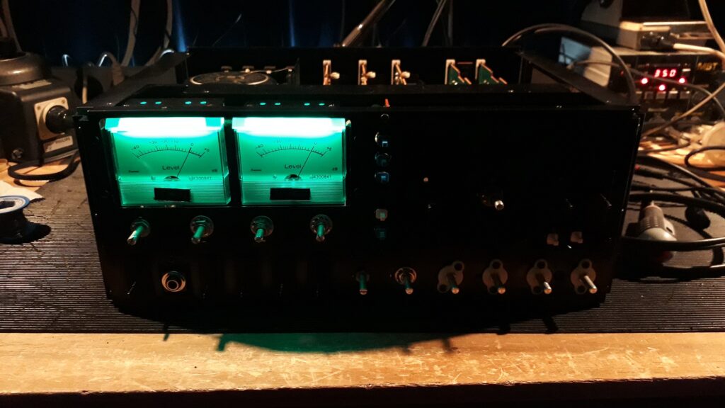
From whatever angle you approach describing this amplifier, there is no way around having to use superlatives. Wether it is the weight of no less than 49 Kg’s, the 2 x 300 Watt power at any load impedance, the magnificent construction, the sound, detailed yet impactful. A true masterpiece, both to behold as well as to listen to.
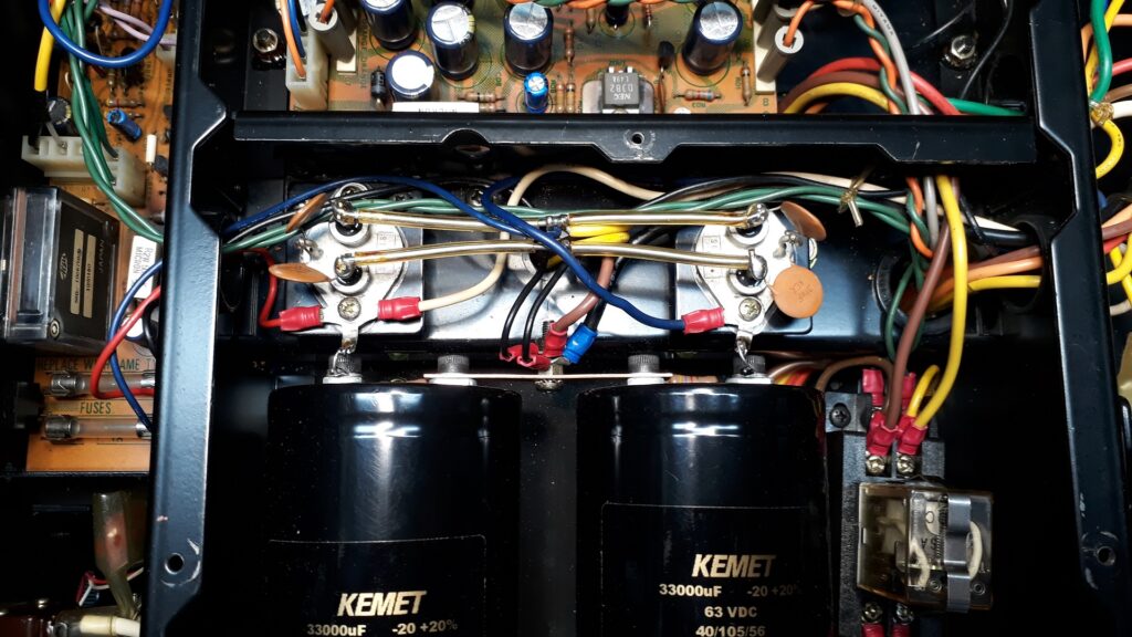
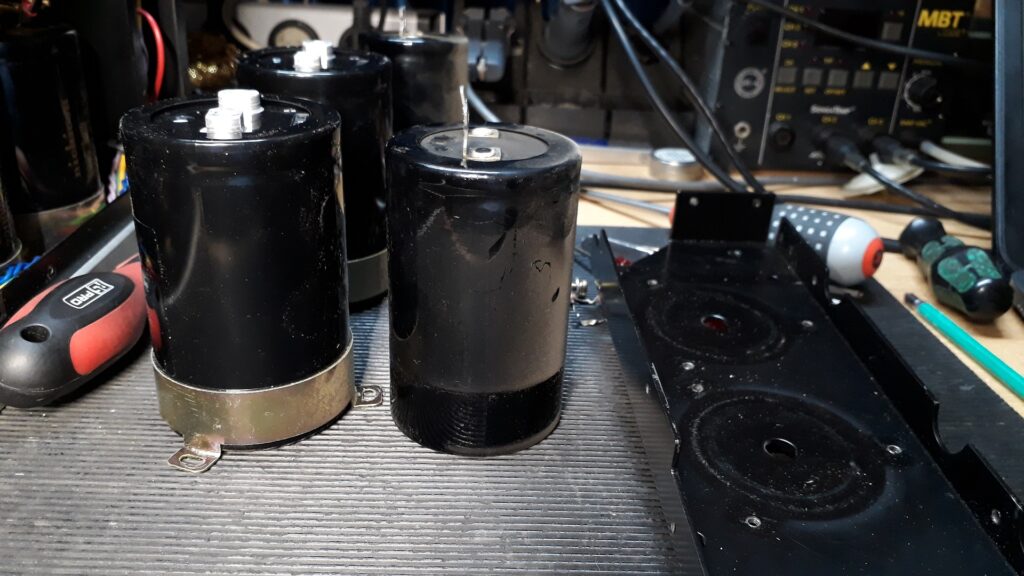
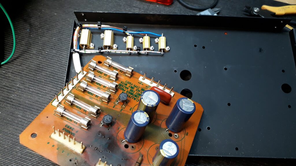
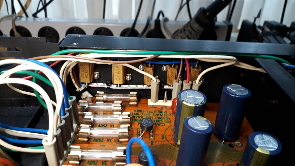
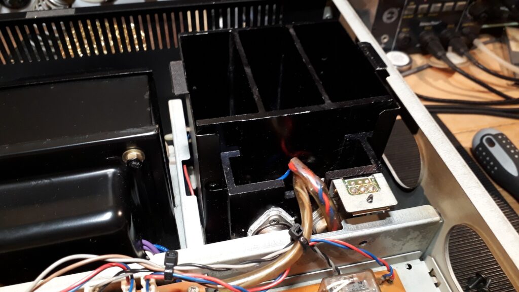
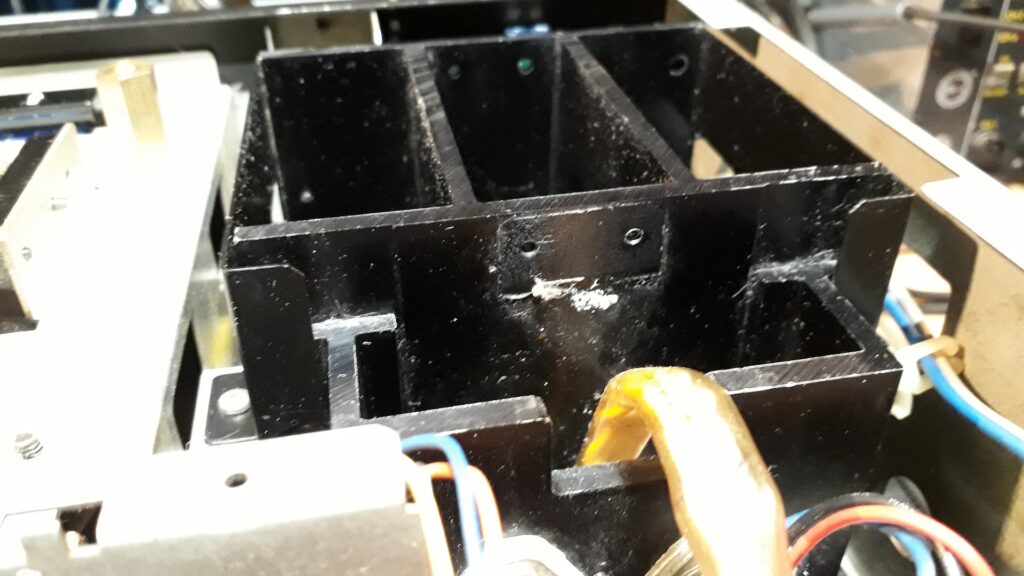
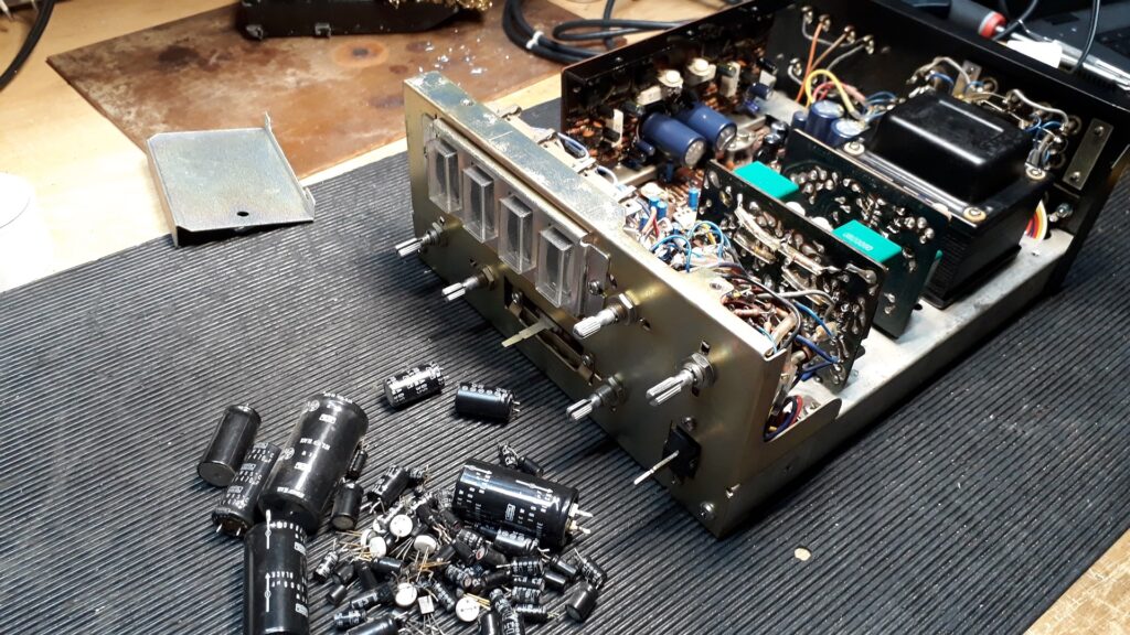
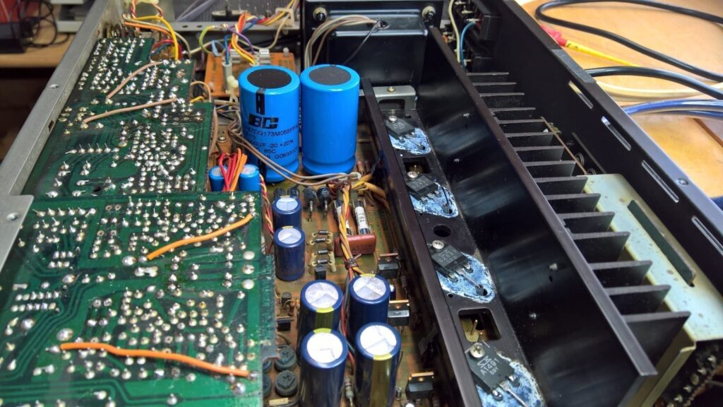
The new KEMET 33000 uF main power supply capacitors were slightly bigger than the original ones, so they had to be ‘shoehorned’ in… The circular clamps holding the capacitors in place are screwed into the side panels with three M4 bolts, but as a consequence of the slightly greater diameter of the new capacitors, the clamps had to be ‘stretched out’ a bit and extra holes had to be drilled into the side panels to make it all fit properly.
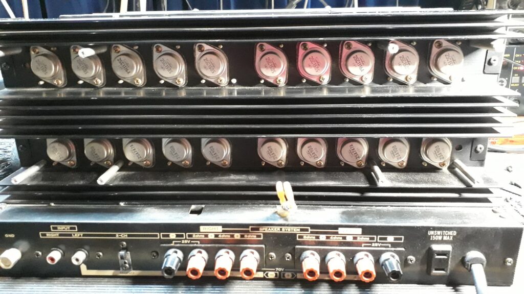
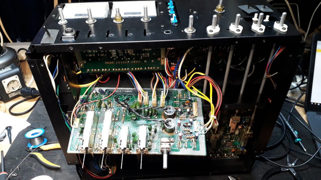
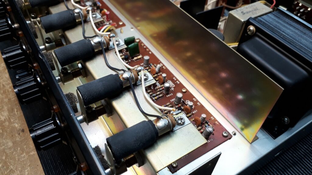
As far as I know the BA5000 is the only Sansui power amplifier to have four push-pull pairs of power transistors per channel. The fifth pair fitted drives the other four. Of course, all Sanken ring-emitter types…
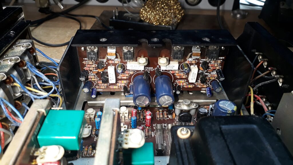
One of the updated driver boards; I use Panasonic FC or comparable high quality electrolytic capacitors to replace the original Elna’s.
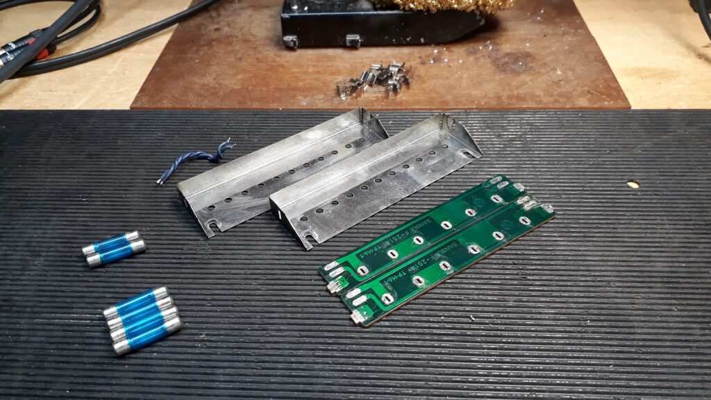
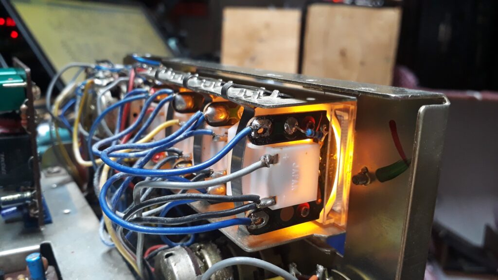
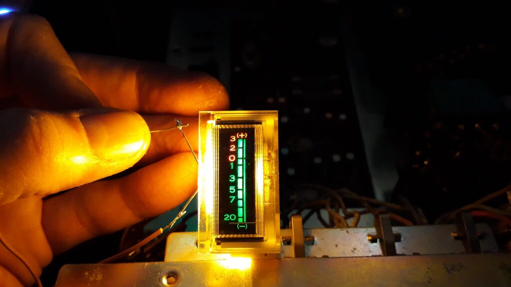
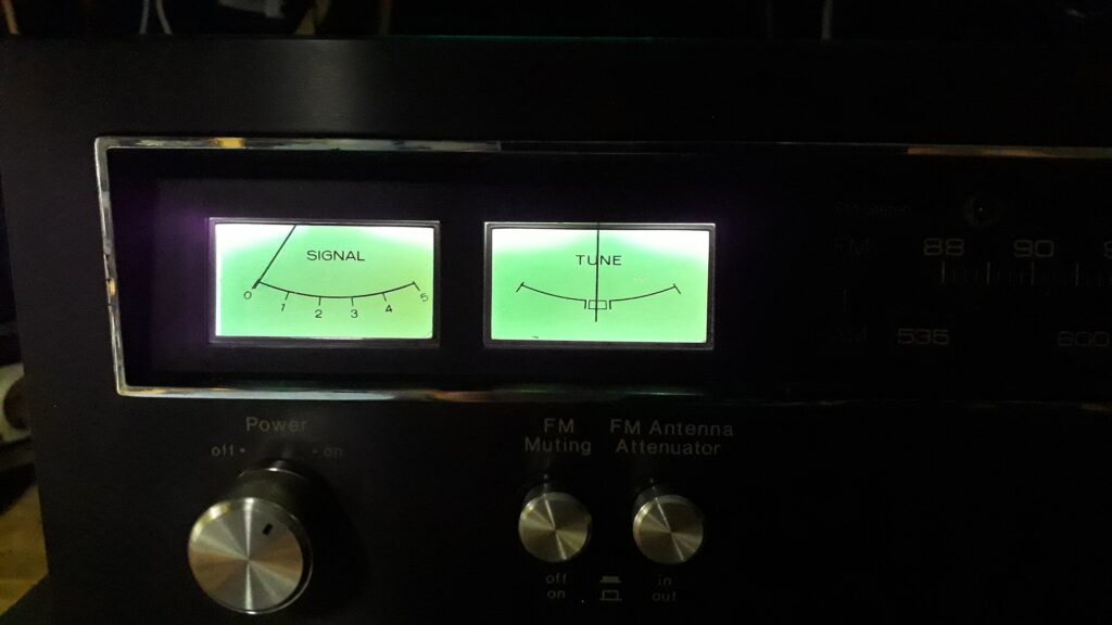
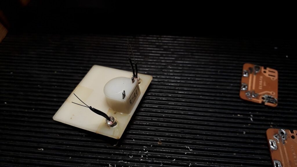
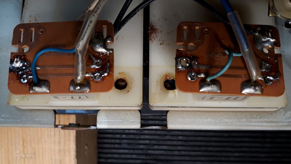
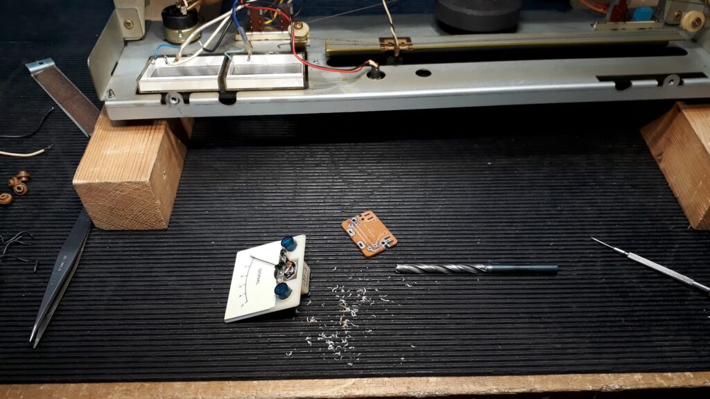
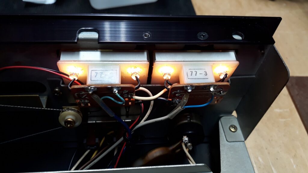
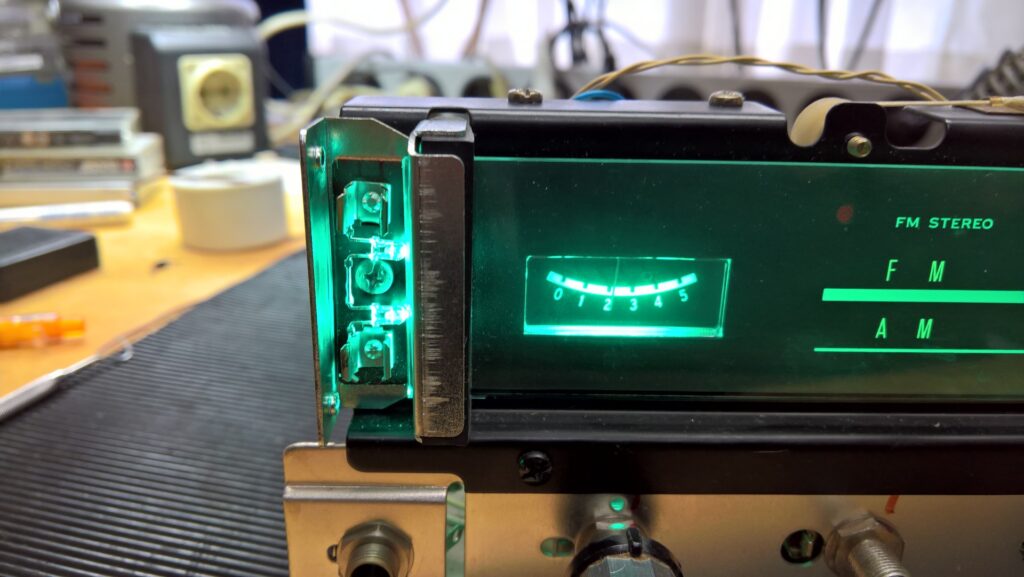
Meter illumination boards and covers all cleaned, removed fittings of the original lightbulbs, ready for the new LED’s, six per meter, two LED’s replacing each original lightbulb.
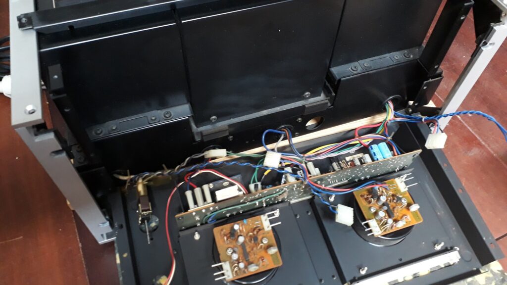
The front panel conveniently ‘folds out’ for access to the input buffer amp board, meter amplifiers and illumination boards.
AU20000:
One of the largest and most complex amplifiers Sansui has ever built, and one of the most beautiful, both to look at and to listen to. Largely a BA3000 and a CA3000 fitted together in one box, everything fits together tightly like a 3D puzzle. All electrolytics replaced, all small transistors replaced, solved the preamp power supply board problem once and for all in the best possible way. LED illumination for the meters, taken apart and cleaned the rotary switches for the tone control, the mute and other switches. Placed a new bi-color LED for on/off/protection indication, fitted new 3-wire mains cable. A true no-compromise AU20000.
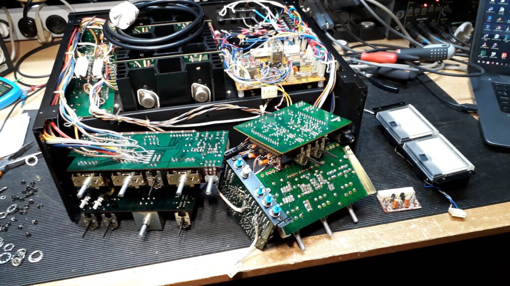
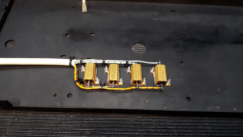
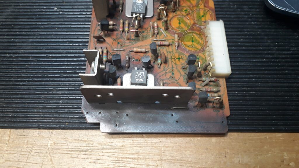
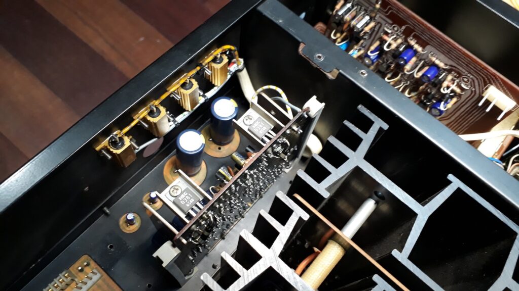
The preamp power supply circuit board is the same as in a BA3000, but since the AU20000 has a complete preamplifier section fitted instead of just a buffer amplifier in the BA3000, this preamp draws much more current than the buffer amp of a BA3000. Therefore the power resistors get much hotter and damage the circuit board. To solve this in a proper way I fitted replacement metal resistors on the inside panel opposite to the power supply board and made a short cable loom to connect them to the appropriate positions on the circuit board. This is a lot of work, but no other method will solve this problem in a way that will last for decades to come.
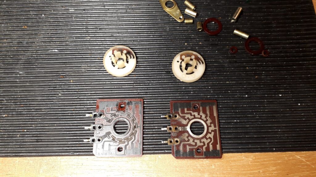
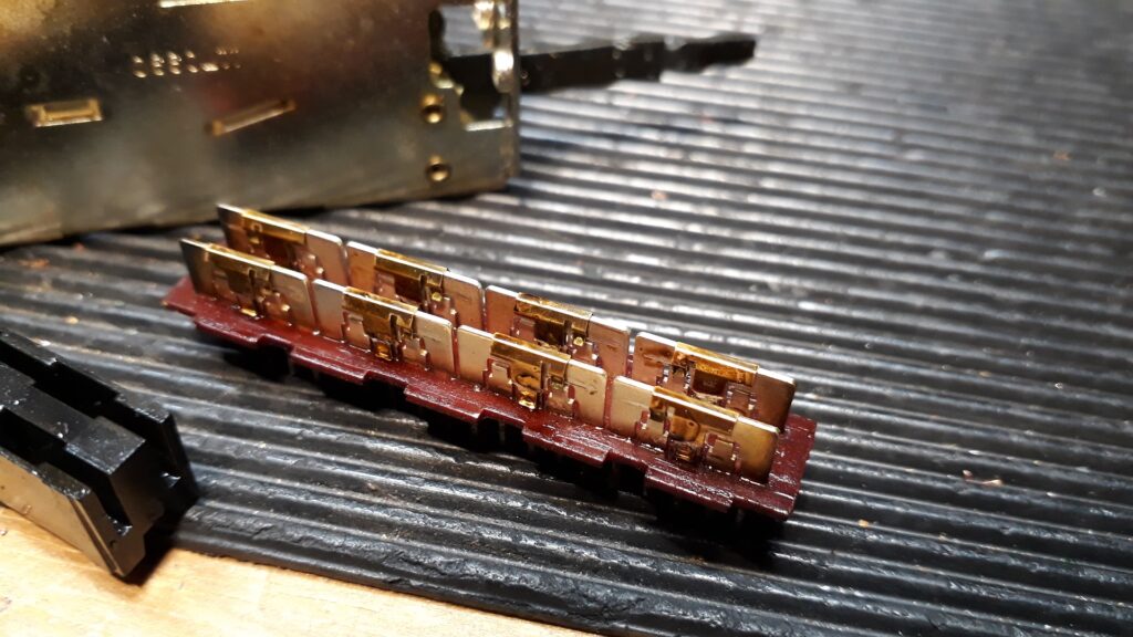
The beautiful stepped tone control rotary switches are often damaged by applying too much contact cleaner. The only way to make them work properly again is to remove them from the circuit board, take them apart and clean with thin machine oil on a cotton swab. The left one before, the right one after cleaning. I use a diamond polishing tool to clean metal contacts, like on the rotary arm of these switches, or relay contacts.
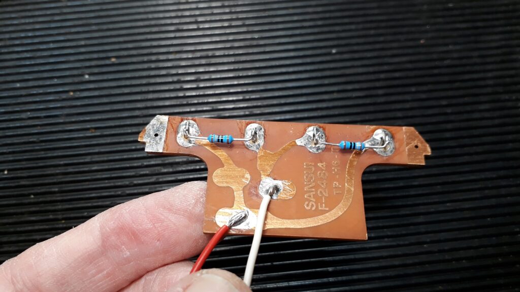
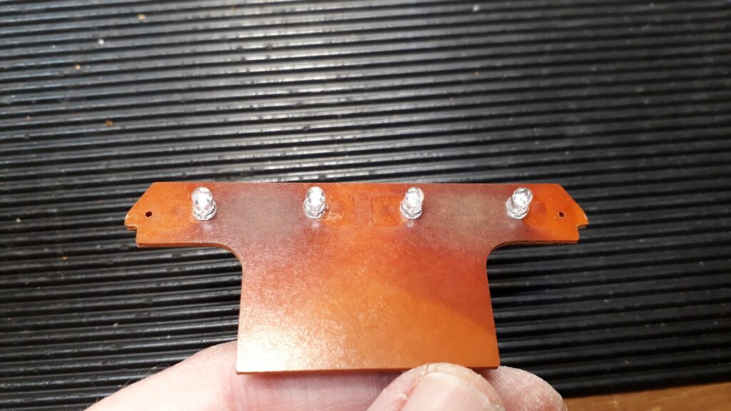
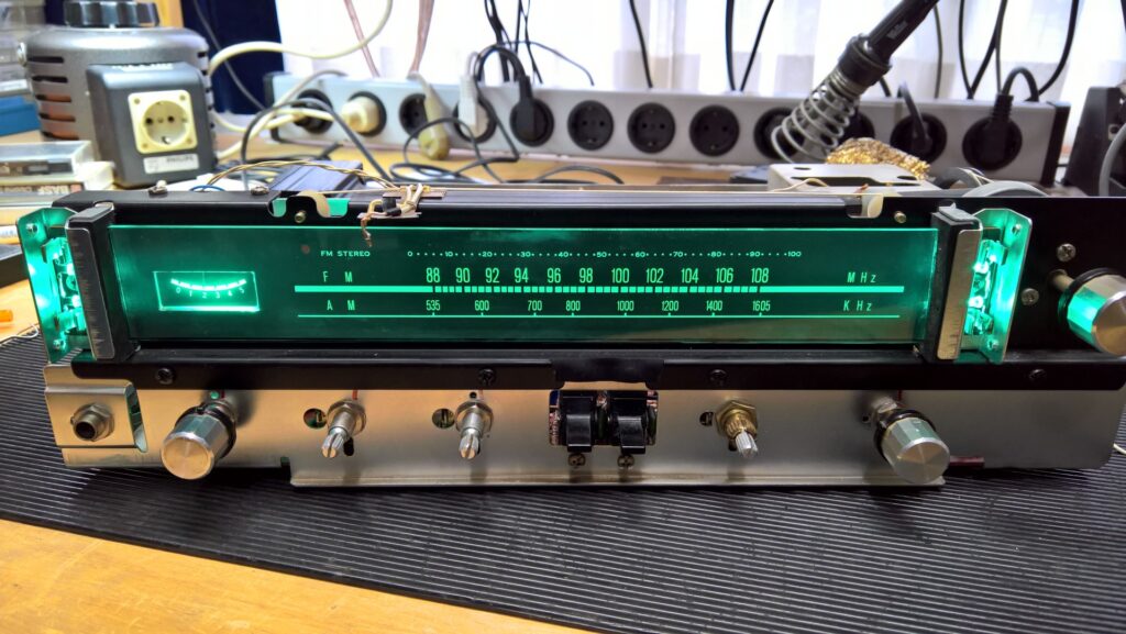
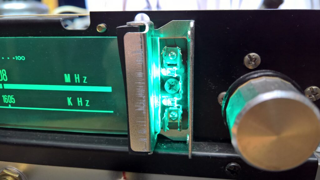
LED illumination for the meters can be a beautiful replacement for the original lightbulbs, but since LED’s have a much more directional lightbeam it is crucial to project this light forward enough and from enough distance to get an equal illumination without any ‘hot-spots’.
The mute switch also suffered from too much and too often applied contact spray. Only solution again is to remove it from the circuit board, carefully take it apart and meticulously clean each and every little contact. Put it back together again, re-solder it into the circuit board, fit the circuit board back into the amplifier and test it.
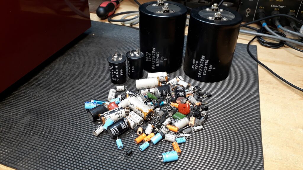
The complete pile of old capacitors and small transistors; more than 80 of each! I also replace most of the small transistors since they almost always have corroded (black) wires. Unfortunately, this corrosion continues inside the actual transistor and inevitably, it will become noisy over time.
CA3000:
Together with the CA2000 and the (much underrated!) CA-F1 one of Sansui’s finest preamps. The line amp board kept me busy for quite some time, repairing all the bad connections between the top- and bottom traces of the board. Like with the BA5000 and the AU20000 I have fitted cyan LED illumination for the meters.
The power supply board of a CA3000 suffers from a similar problem as the preamp power supply board of an AU20000; resistors that get too hot and damage the circuit board. The proper way to solve this problem is to fit metal replacements on the inside of the adjacent inner panel for cooling and make a small cable loom to connect them to the appropriate positions on the circuit board.
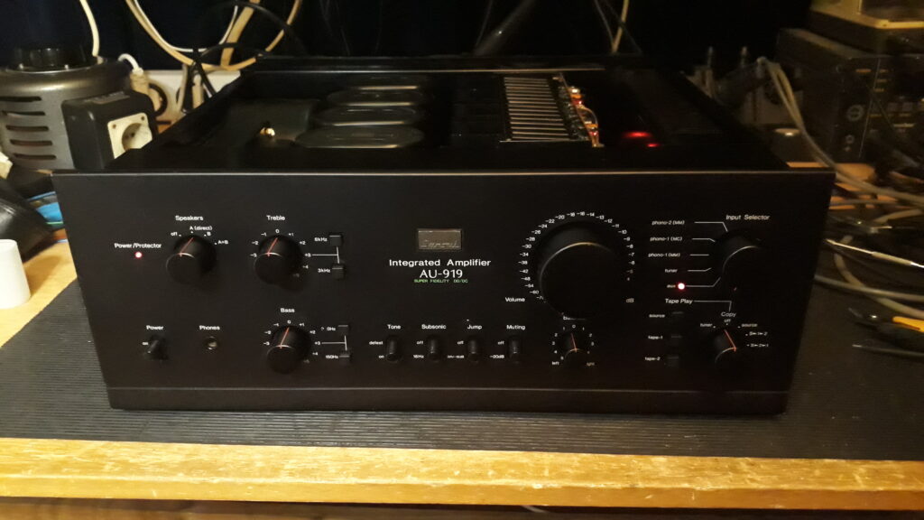
AU919:
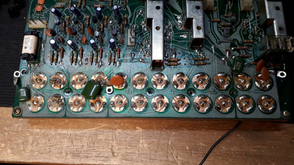
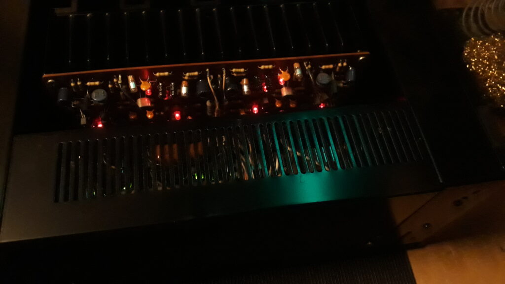
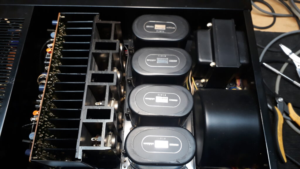
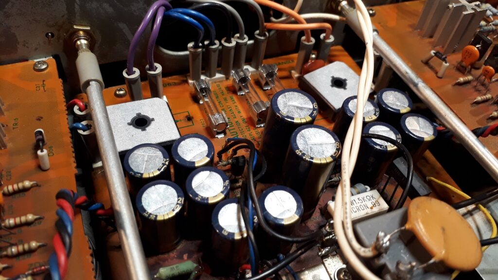
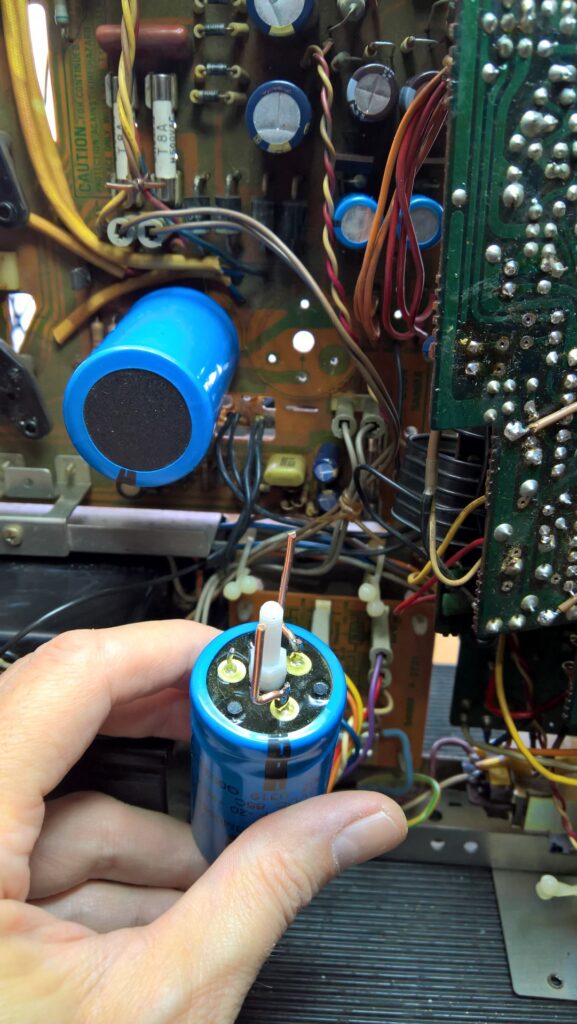
Complete overhaul, all electrolytics replaced, including the ‘big four’ which originally contain two capacitors each, so in each I put two new Kemet/Rifa 15000 uF 63 Volt. Of course all the notorious ‘black-flag’ capacitors are replaced, as well as the triple diodes in the power amp and the MD phono preamp. This replacing of the triple diodes is not stricktly necessary but I replaced them with LED’s which just looks nice…
Only recently I compared the AU20000 with the AU919 and although both sound stunningly good, I found the 919 to be slightly more refined and having a better stereo imaging, I suppose this is largely due to the far superior power supply of the 919, but also the presence of the DD/DC circuit.
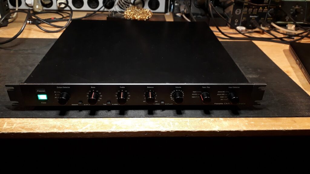
CA-F1:
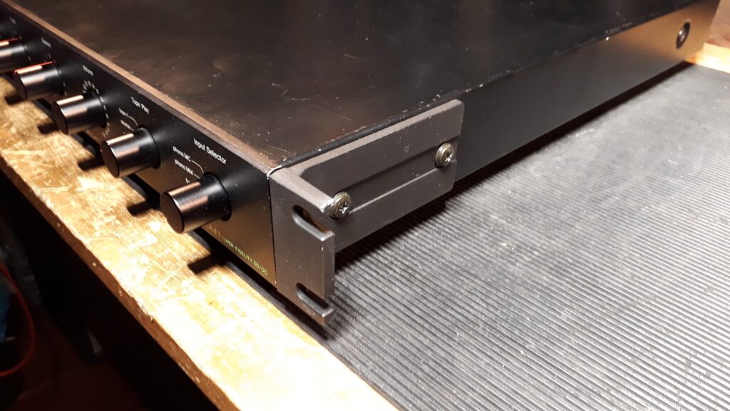
Underrated but certainly one of the most understated of any device that Sansui has ever built. Sleek, minimalistic in every sense, but of an incredible build quality and the sound is just stunning. From the elegant but superbly stable power supply to the perfectly shielded box-in-box construction for the MC phono preamp, the famous DD/DC circuit integrated in the MM phono stage and a line amp stage that is derived from the AU-X1 flat amp, this is a gem! This unit has had full recap, the line stage problem of the overheating driver transistors is solved and this particular unit comes uniquely fitted with the original rack handles!
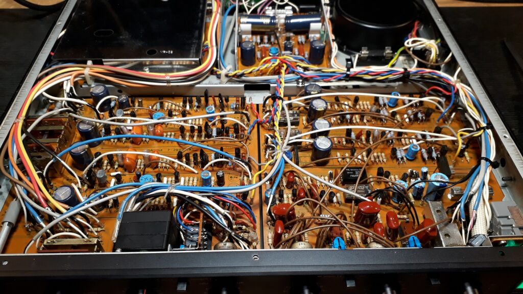
A CA-F1 is built upside-down, so the picture below shows the unit from underneath. The wiring may look untidy, but a deliberate choice has been made to carefully separate the signal wiring from the power wiring as much as possible to avoid any interference. The unit is easy to work on, only the top- and bottom covers need to be removed.
BA-F1:
An utterly refined and relatively understated power amplifier. Sadly Sansui decided to fit a conventional power transformer instead of a toroidal one. This makes the BA-F1 lack impulse power to drive difficult loads, but combined with a set of high efficiency (Tannoy) speakers, this is breathtakingly beautiful.
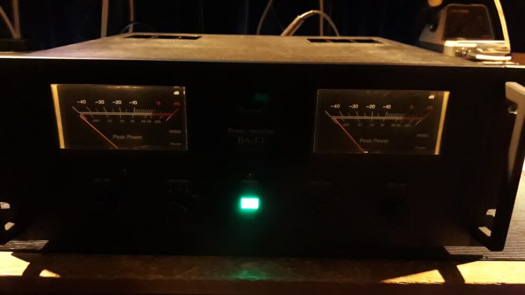
This unit is fully recapped and the thermal sensing transistor is moved to the top of the heatsinks. Oddly enough originally this sensing transistor is placed at the bottom of the heatsinks, where they are coolest. This means the unit can run hot if driven hard or (as I do) when the bias is increased for better sound quality. Once the sensing transistor is placed at the top of the heatsinks this issue is solved.
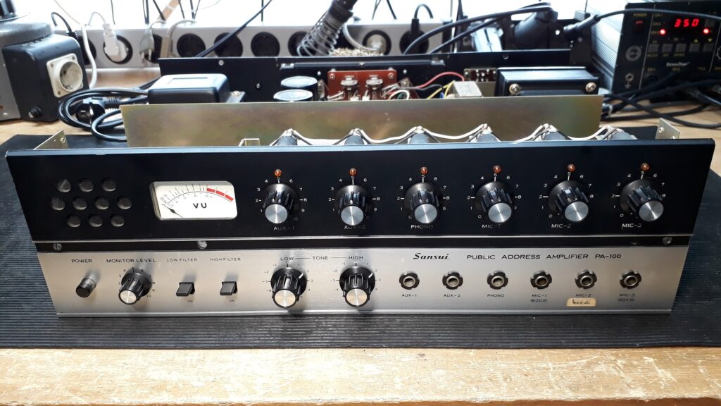
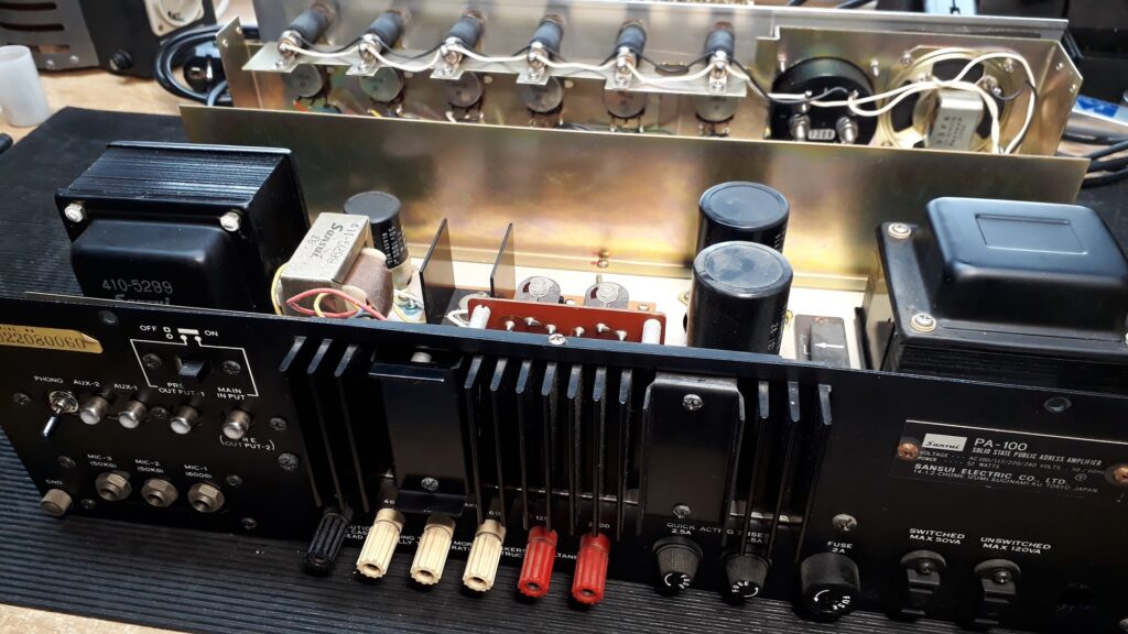
PA100:
Not exactly ‘hifi’, not even stereo, but still a true Sansui, by sound, by buildquality, by everything. A rarity in my country, because in the late 1960-ies, a Sansui would not have been the obvious choice for a 100 Volt PA amplifier to drive a few dozen ceiling mount speakers in a small supermarket.
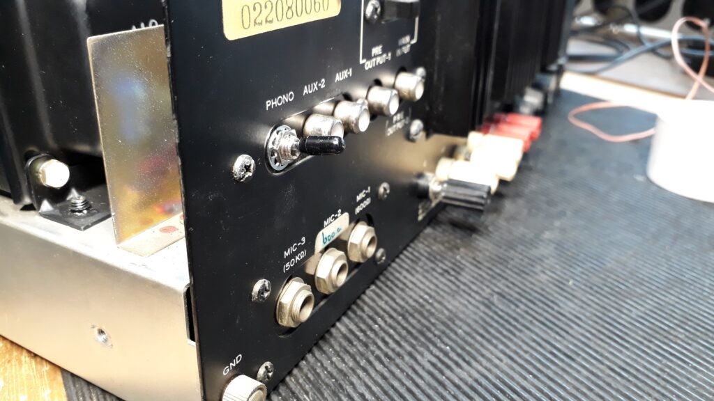
The owner of this one has a small recording studio and asked me to convert Mic 1 and Mic 2 inputs to not only accept a balanced microphone signal, but also to have phantom power for condensor microphones. I fitted two new 2:1 audio transformers to replace the original 1:10 ones and agreed to sacrifice the RCA connector on the back panel for the phono input to fit the on-off switch for the phantom power. The line amp turned out to be very noisy, so I had no choice but to replace all the small transistors and some of the composite carbon resistors, mainly on the input side, where they contribute most to the noise. The power amplifier has two transformers in the signal path, one interstage transformer to drive the two power transistors, and an output transformer, to allow for various output impedances, from 4 Ohms to 125 Ohms, to drive 100 Volt speakers. I chose not to replace any of the original lightbulbs, since they were all working fine. Once they start to fail, they will be replaced by LED. For now, I kept as much of the original amp as possible.
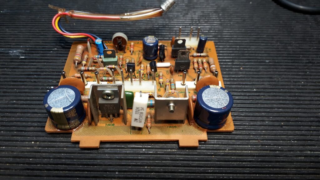
Today the owner let me know that the sound of the mic preamps rivals that of many ‘high-end’ preamps for musicality and clarity. I converted the inputs on the back panel to be direct outputs for the four preamps, but it can still be used as a mixer amp with a summing output via the line stage. Essentially the mic preamps consist of only two transistors. Proof once more that less is more.
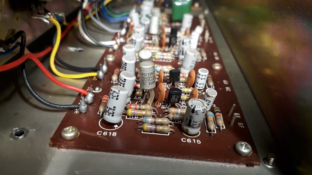
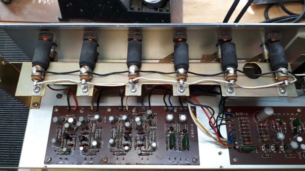
The microphone preamplifiers; only two transistors per channel, the metal can Hitachi on the left is original, the 2SC2240 is the only new component. Deliberately chose to not replace the capacitors, to keep the amplifier and its ‘sweet Sansui sound’ as much intact as possible.
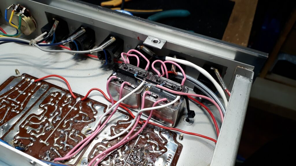
The two new microphone balancing transformers.
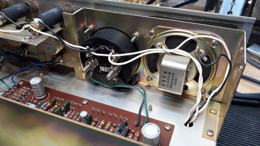
The PA100 has both a signal level meter that monitors the preamp output level as well as a small monitor speaker with a seperate volume control to monitor the speaker output.
Simple yet elegant solution; a small metal lip, attached to the volume control rod, connected to the potentiometer rotates away from the lightbulb (in the black sleeves) thus illuminating an amber bead in the front panel, indicating the being active of that channel.
QS100 4-channel rear amplifier/decoder.
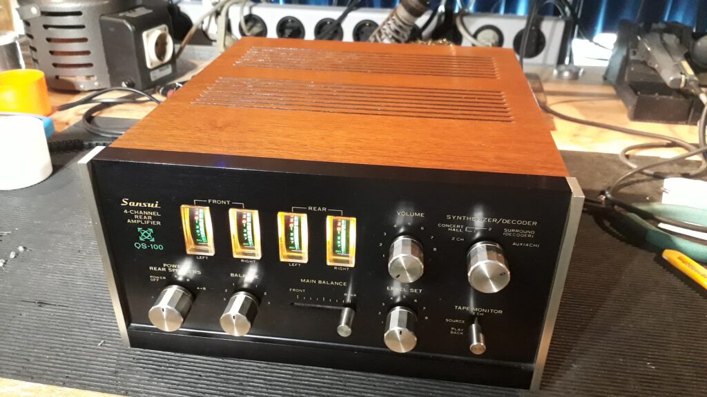
Replaced all electrolytics and small transistors, fitted LED illumination for the meters, fully serviced and adjusted.
The power amplifer of this QS100 is almost identical to that of an AU101 or an AU222, so if you connect this unit as if it is a stereo amplifier, connecting a signal only to the rear inputs and setting the input switch to AUX/4CH, you will have the sound quality of an AU101 or AU222… The decoder uses patented modules for the 4-channel quadrophony effects. I have tried this and although it sounds nice, I would still prefer to use it just as a stereo amplifier.
AU-G90X
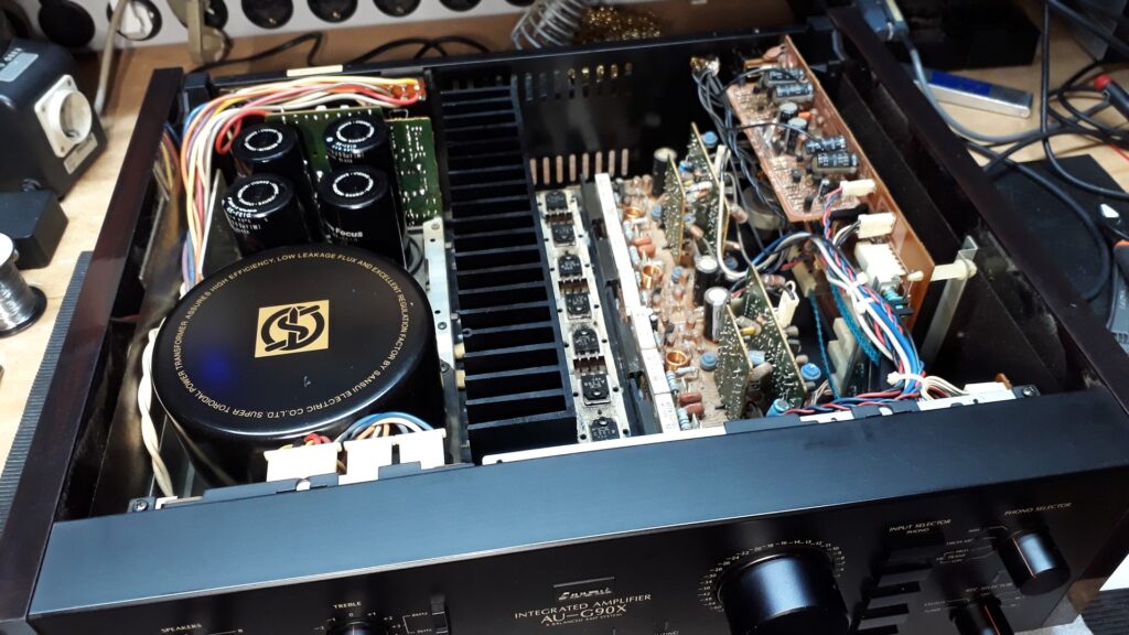
One of the later series of top models, manufactured from 1984 to 1986. The ‘X’ indicates the X-balanced circuitry, essentialy four power ampliers, two per channel, one of each is 180 degrees out of phase with the other. The in-phase output is connected to the positive output terminals, the out-of-phase output to the negative output terminals.
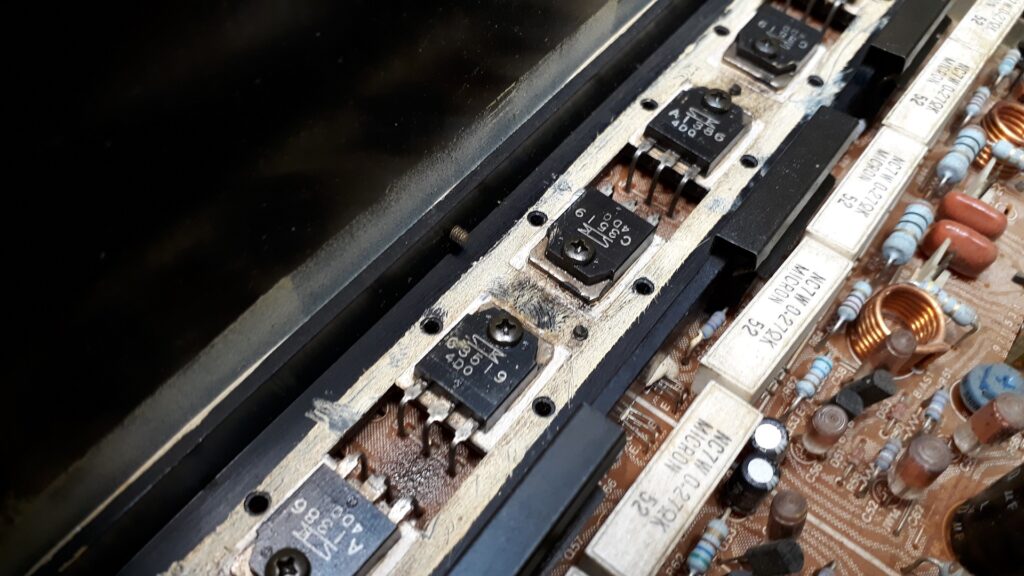
Adjusting the DC-offset and bias is a delicate operation, no less than eight adjustments have to be done, in the right order. I prefer to replace the original trimmer potentiometers for multi-turn types to make adjustment a little easier, but the owner of this unit wanted only basic service to be carried out.
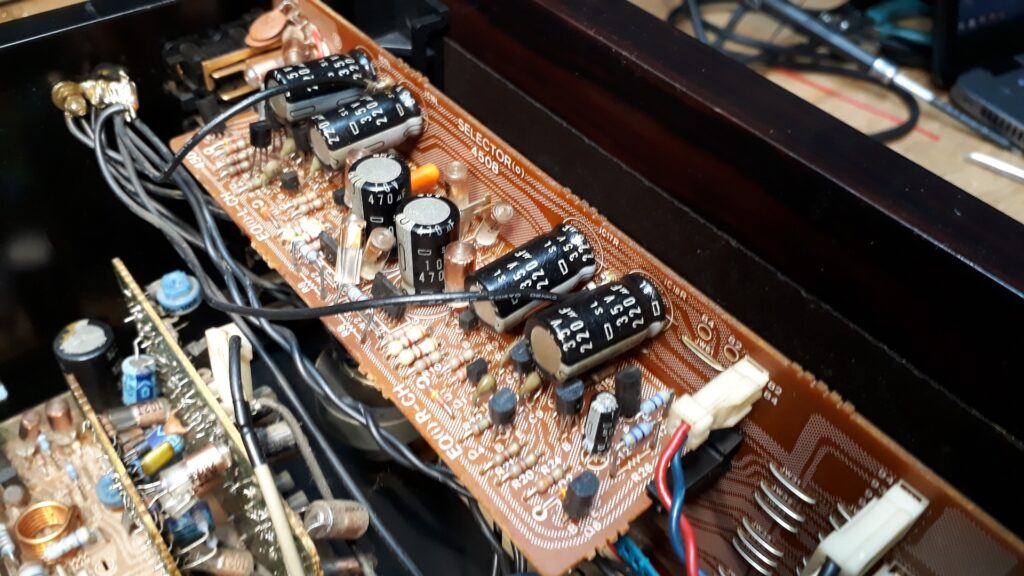
Cleaning the unit it became obvious that the previous owner was a smoker. Generous amounts of oil based cleaning solvent made the unit as good as new again. The main power capacitors measured ok, still having full capacitance. Soundwise I recommended replacing all the small electrolytics, which I am confident will make the amplifier sound much more transparent and dynamic.
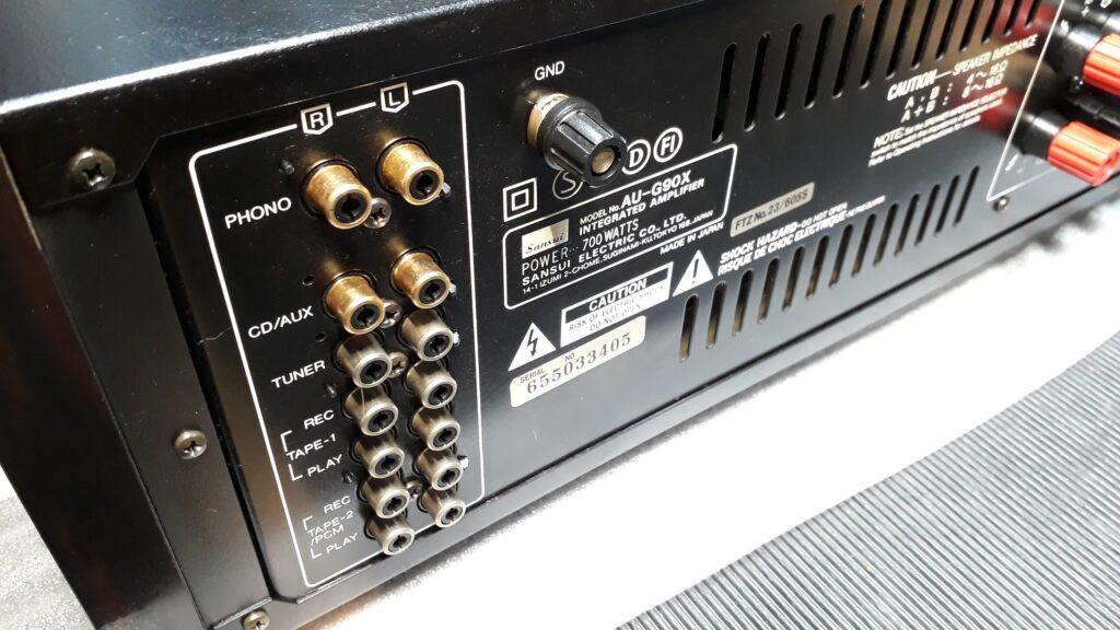
The owner told me the unit suffered from signal dropout. Usually this relates to corroded contacts of the speakers relays. Removing them in order to clean the contacts is quite an undertaken in this model; the entire back panel has to be removed and the speaker terminal block has to be removed from the circuit board before the relays can be removed from the circuit board. The contacts were indeed corroded, confirming the complaint. Because of its massive toroidal power transformer this model has a soft-start circuit, reducing the otherwise substantial inrush current on switch-on of the unit to manageable proportions. The relay for this circuit sits on the same circuit board as the speakers relays, so it is little extra effort to clean the contacts of that relay as well.
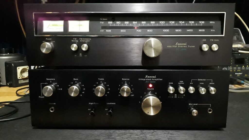
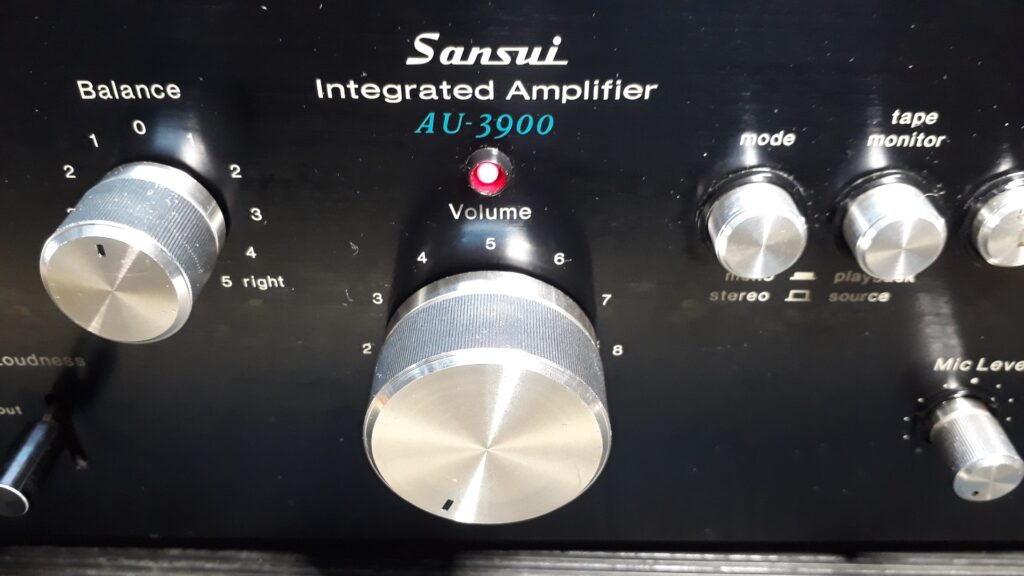
AU/TU3900:
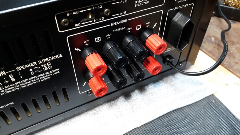
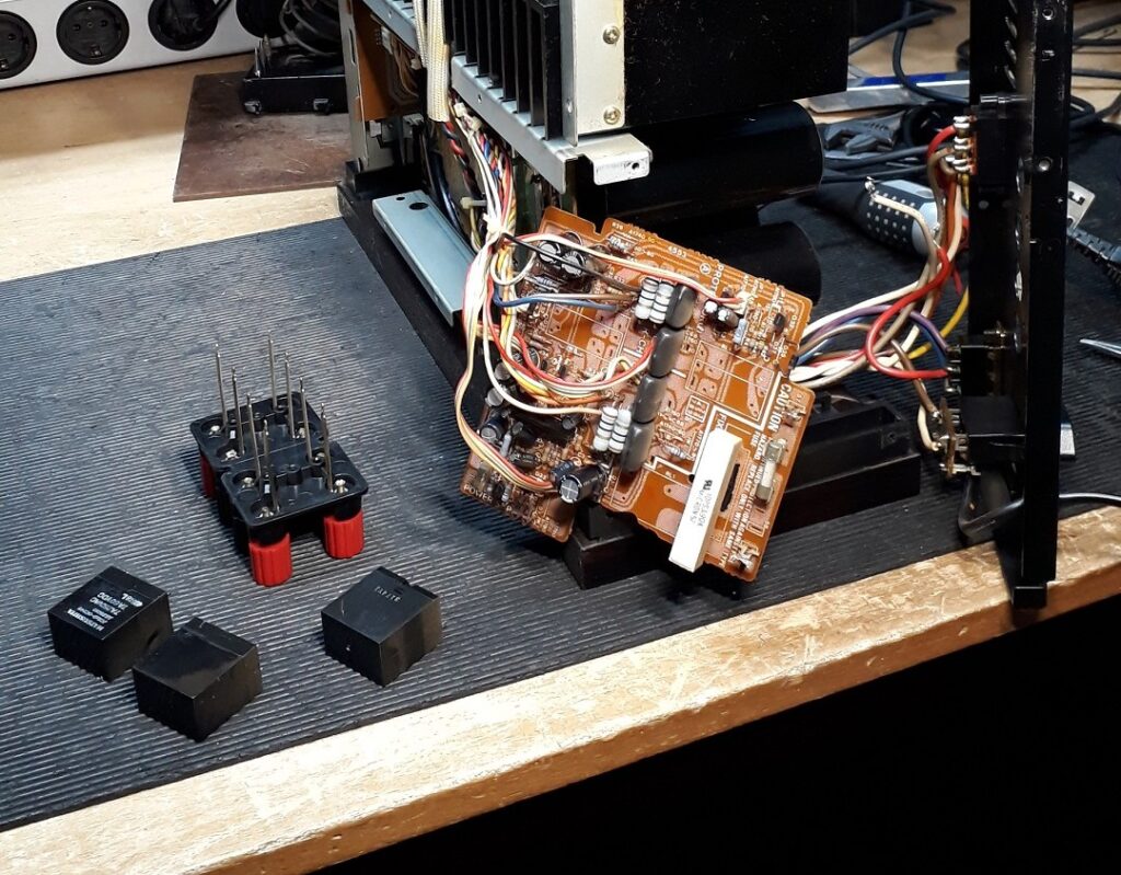
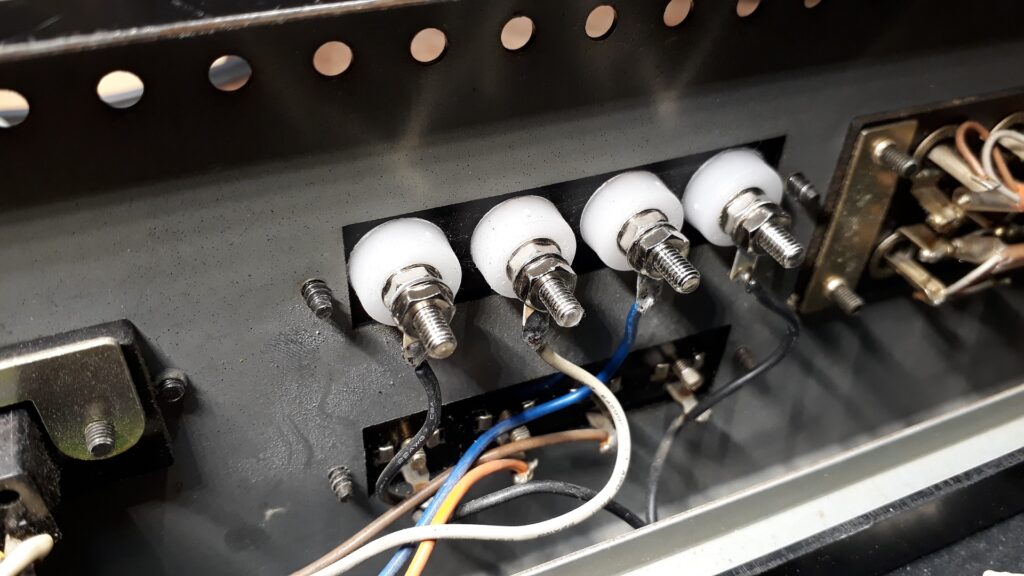
Only small electrolytics replaced, all small transistors with the corroded wires replaced, new LED for on/off indication placed, new speaker terminals for speakers A. However good they may be, I refuse to install gold plated terminals because I think it looks tacky on an old amp like this…
Soundwise I like the AU3900 and in general this series for its ‘sweetness’ for which Sansui is well known.
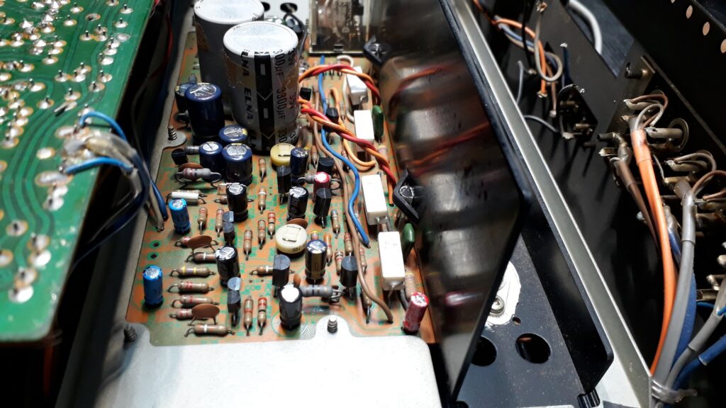
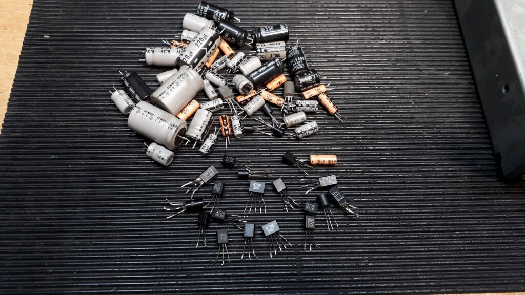
In many Sansui (and other) amplifiers of the early ’70-ies these transistors can be the cause of a lot of problems, usually noise and ‘crackling’ in the sound. The black corroded wires of these transistors are indicative of this problem. Replacing them all is the only proper solution.
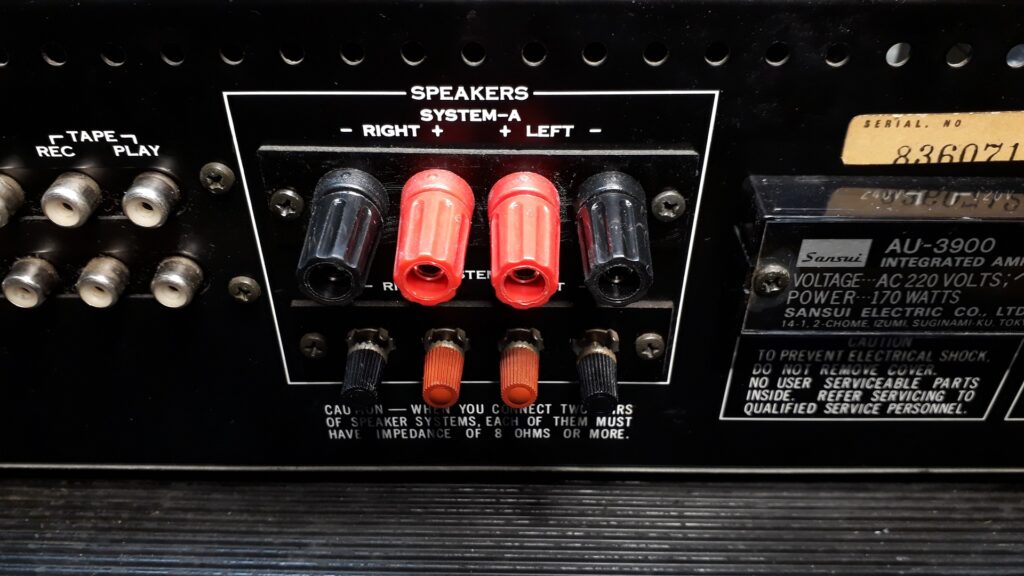
Tidy and sturdy; new red and black terminals replacing the somewhat flimsy original connectors, at the same time allowing for 4 mm banana plugs to be used.
Replacing the lightbulbs in the two meters by new incandesant bulbs was the most beautiful way, if only they would have fitted… Removing no more than one mm of plastic from the holes in the back plates of the meters without damaging anything takes patience and a steady hand.
Model 210 receiver.
All electrolytics replaced, stereo decoder repaired, amplifier modified with bias control (originally not present!) and installed LED scale, meter and indicator needle illumination. Meticulously cleaned inside and out by a good friend of mine. Modest power, only 2 x 12 Watts at 8 Ohms but with original Sanken power transistors a true joy to listen to with a sensitive pair of speakers.
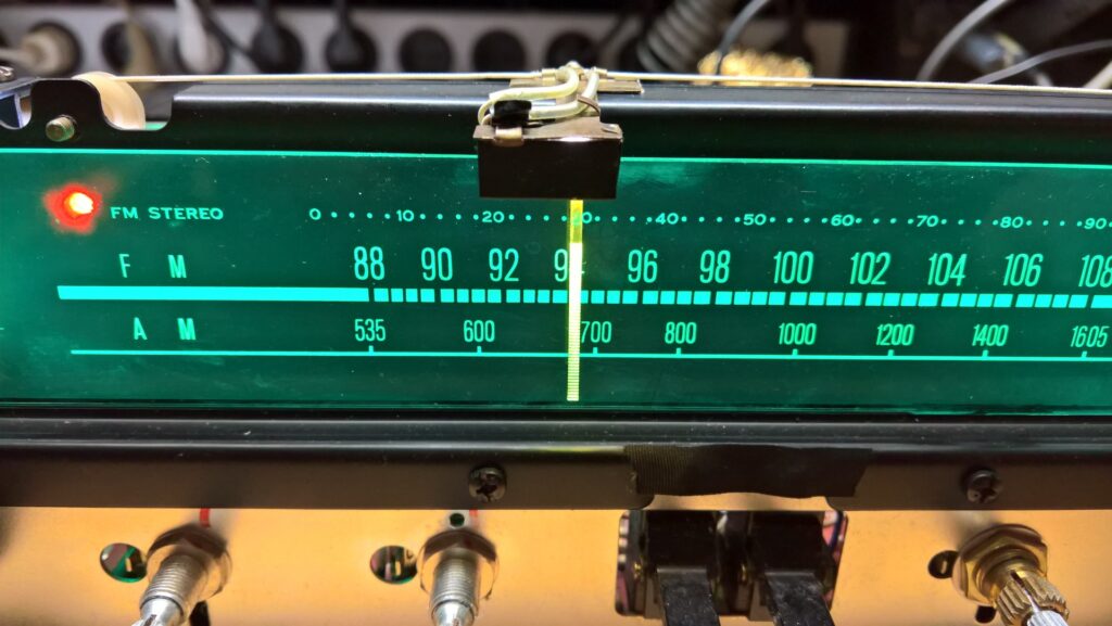
Fitting a 3 mm white LED inside the little metal box from which the indicator needle hangs was another one of those extremely fiddly jobs. The beam of light had to be directed exactly downwards into the needle to properly illuminate it. I filed a little aluminium bushing to the exact size, fitted the LED and glued it into position inside the metal box. Soldered the very thin wires to the LED and put it back together again. Very carefully of course, not to break or damage the nearly 50 year old string that moves the needle up and down the scale…
AU317:
Perhaps one of the most versatile amplifiers that Sansui has ever built and one of my all-time favorites; compact in size, powerful enough to drive most speakers, originally equipped with the beautiful Sanken power transistors, but they are easy to replace with newer model Sanken transistors if necessary. Easy to modify and service. A beautiful, very ‘lively’ and musical sounding amplifier. A Swiss army knife among amplifiers.
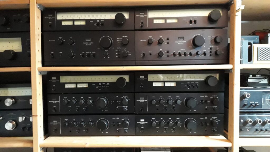
A small part of my Sansui collection.
In this AU317 I fitted main capacitors that required a little creativity; I glued nylon M4 bolts onto the bottom of the capacitors with 2 component epoxy resin glue, bent two pieces of 2.5 qmm installation wire to the correct soldering positions into the circuit board and after placing, added a 4 mm nylon nut to tightly fix the capacitor into position. The large centre hole where the 4 mm bolt fits through is originally already present in the circuit board, so no drilling needed. Soldered the wires and ready to go.